

SETUP & BASICS
01
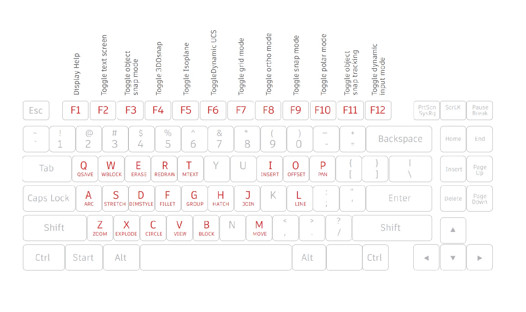
Keyboard Shortcuts
Take advantage of AutoCAD-specific keyboard
shortcuts to save you valuable time. You can even
create or modify the existing shortcuts.
1. Click Manage tab > Customization panel > User Interface, or type CUI into the command line.
2. In the Customize tab, Customizations In pane, click the plus sign (+) next to the Keyboard Shortcuts node to expand it.
3. Click the plus sign (+) next to the Shortcut Keys. • To create a shortcut key, in the Command List pane, drag a command to the Shortcut Keys node in the Customizations In pane. • To modify a shortcut key, select a shortcut key from under the Shortcut Keys node.
02
Autosave
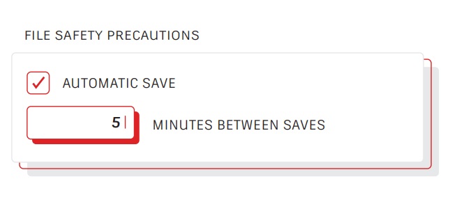
Set your Autosave setting to 5 minutes (or 2 or 3
minutes!), and manually save often with the QSAVE
command or Ctrl+S shortcut.
Automatic save files are backup files created automatically by the
Autosave feature. Set the number of minutes between automatic
saves in the Open and Save tab in the Options dialog box or by using
the SAVETIME command. Automatic saves are only done if a drawing
has been modified after the last save. QSAVE, SAVE, and SAVEAS will
delete the current .sv$ file – the Autosave file only remains if the
application closes unexpectedly.
Find the location of your autosave files by going to the Files tab in the Options dialog box and inspecting the Automatic Save File Location folder in the hierarchy, or by using the SAVEFILEPATH command. Once you find the file, change the file extension from .sv$ to .dwg to open
03
Quick Access Toolbar
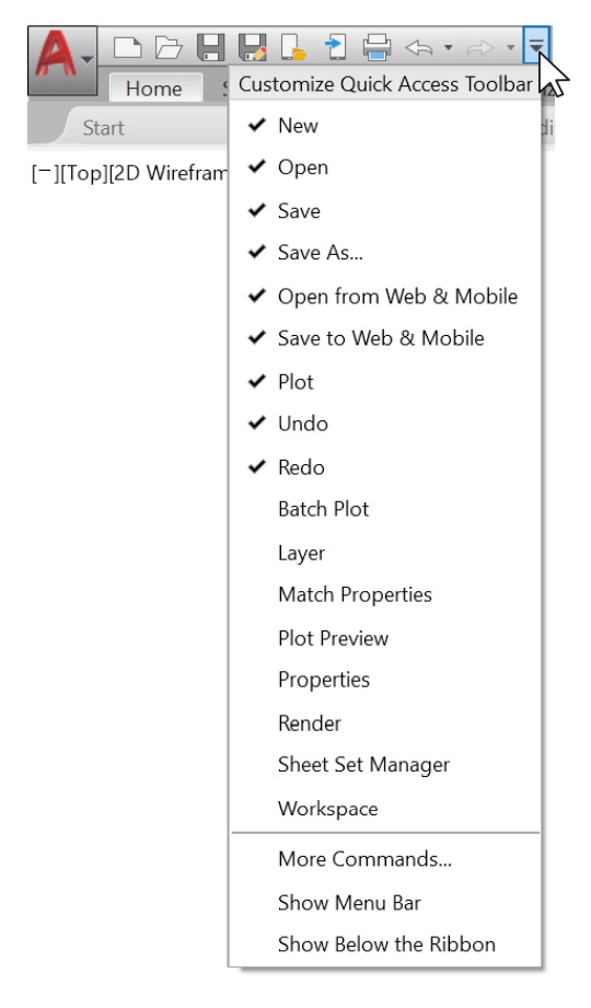
Keep your most frequently used tools in the Quick
Access Toolbar (QAT) right at the top of your screen.
Customize the QAT by clicking the small, pull-down
control button on the right. You can check and
un-check the commands you want quick access to.
Here, you can also change where the Quick Access Toolbar docks, or even turn on the old-style Menu Bar. You can also drag the elements within the Quick Access Toolbar to change the order in which they appear.
04
Right-Click
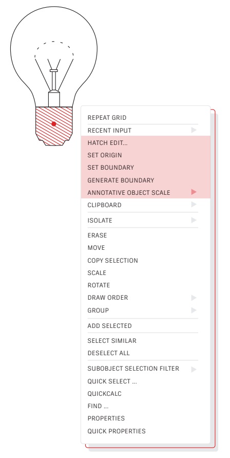
Right-click to access contextual popup menus,
a productivity enhancement favorite. Since the
menus are contextual, you get commands that
are specific to what’s selected
If you’re someone who uses a mouse right-click as ENTER, you can still have the best of both worlds. It’s easy using this time sensitive right-click feature. To turn it on, simply call up the Options dialog box, go to the User Preferences tab, and then select the Right-Click
Customization button. You’ll get a second dialog box that contains the control for time-sensitive right-clicks.
When enabled, right-click will still function as you prefer, with a
single, quick click working as ENTER, but now, by holding down the mouse button just a little longer – a quarter of a second by default – you’ll get the contextual popup menu instead
05
Layers
Resist the temptation to create everything on
one layer. Organize your drawings by assigning
objects to layers that are associated with a specific
function or purpose, for example, walls on one layer
and doors on another layer
With layers, you can:
• Associate objects by their function or location
• Display or hide all related objects in a single operation
• Specify linetype, color, line weight, and other standards for
each layer
To see how a drawing is organized, use the LAYER command to open the Layer Properties Manager. You can either enter LAYER or LA in the Command window, or you can click the Layer properties tool on the Home tab of the Ribbon
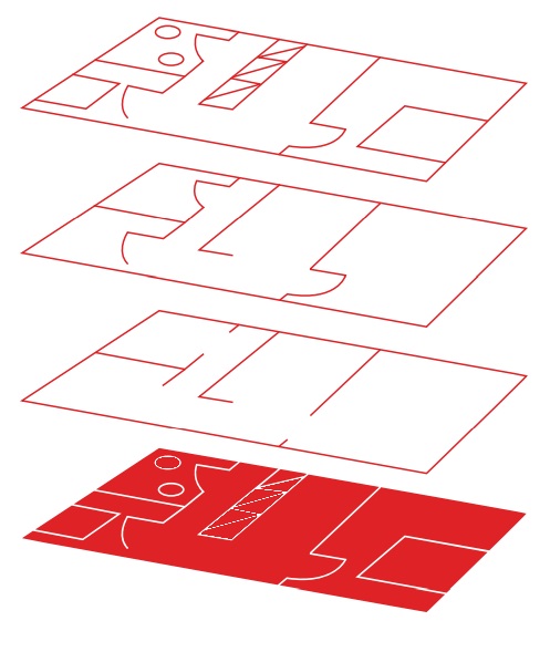
06
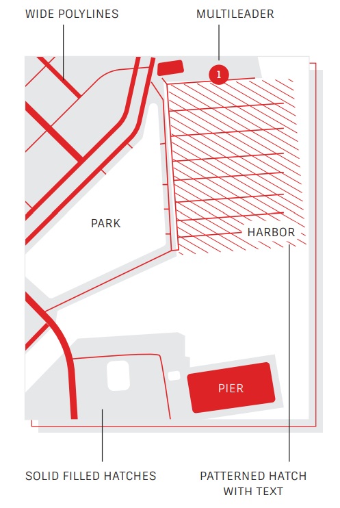
Draw Order
Control how objects overlap and the order in which
they’re displayed with the Draw Order command.
Set up your Draw Order with “Bring Annotations to
Front” and “Send Hatch to Back”.
In the Home tab of the Ribbon, click the Modify panel drop-down list, and select Draw Order (or use the DRAWORDER command). Choose one of the displayed options, select the objects you want to modify, and press Enter.
In general, you will want to display and plot annotation objects in front of other objects, and hatches and fills behind. Wipeout objects are intended to provide a blank area for adding text without modifying the objects underneath.
NOTE: You can control the draw order of overlapping objects only within the same space: model space or paper space.
VIEWING
07
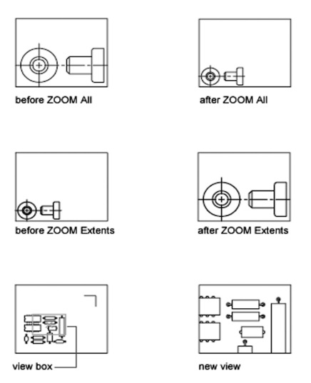
Zoom
Follow the prompts displayed after the ZOOM
command to view your drawing exactly how you
wish. “ZOOM > All” adjusts the magnification of
the drawing area to show all visible objects or
the drawing limits set with the LIMITS command.
“ZOOM > Extents” displays the maximum extent of
all objects.
“ZOOM > Dynamic” pans and zooms using a rectangular view box. The view box represents your view, which you can shrink or enlarge and move around the drawing. Positioning and sizing the view box pans or zooms to fill the viewport with the view inside the view box. (This is not available in perspective projection.)
08
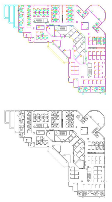
Display Plot Styles
View your drawing in AutoCAD as it’s going to look
when it’s printed by selecting “Display Plot Styles”
in the Page Setup dialog box.
AutoCAD displays drawings in color and then translates the drawing data to a different printed format. Typically, we need to do a plot preview to see what the layout is going to look like when plotted, but you can change this via Display Plot Styles. Set your main layout in this way or create a separate layout to act as a “live” preview so that you can still work in your traditional colored layout view.
09
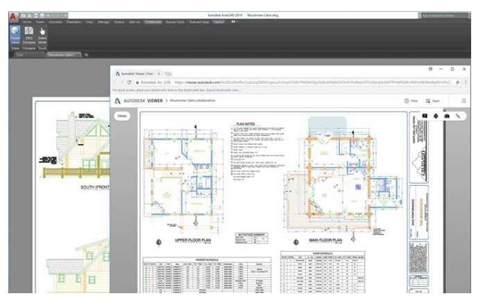
Shared Views
Share designs easily within or outside your
company using the Shared Views feature – without
releasing your original DWG files. Instead of a PDF,
share a link that can be viewed and commented on
in any browser.
Avoid the cumbersome commonly-used workflow of publishing and emailing designs via DWF or PDF files. Instead, a viewable file is created in AutoCAD and circulated via a shareable link that can be viewed and commented on in the browser of any device with internet access. Comments that collaborators make on the shared link appear right back in your AutoCAD desktop product.
The Shared Views feature can be accessed from AutoCAD’s Application menu, under Publish.
OBJECTS
10
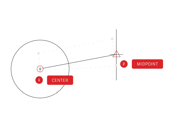
Object Snaps
Use Object Snaps (OSNAP) to draw objects precisely
in relation to other objects in your drawing. For
example, you can use object snaps to create a
line from the center of a circle to the midpoint of
another line.
You can specify an object snap whenever you are prompted for a
point. By default, a marker and a tooltip are displayed when you
move the cursor over an object snap location.
To specify an object snap at a prompt for a point, you can:
• Press Shift and Right-click to display the Object Snap
shortcut menu
• Right-click and choose an object snap from the Snap
Overrides submenu
• Enter the name of an object snap
• Click an object snap button on the Object Snap toolbar. This
will turn on running object snaps that will persist through all
subsequent commands
11
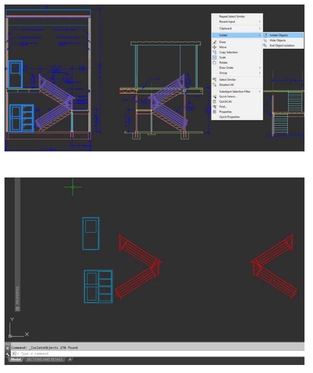
Isolate Objects
Isolate a selected group of objects for easier
editing in complicated or busy drawings. The Isolate
Objects tool (ISOLATEOBJECTS) makes non-selected
objects in the drawing temporarily invisible.
Start this command from the Right-click menu or by typing
ISOLATEOBJECTS into the command line. When you are finished editing or working in the cleaned area of your drawing, you can end your object isolation and bring back any hidden objects simply by using the UNISOLATEOBJECTS command or End Object Isolation right-click option.
12
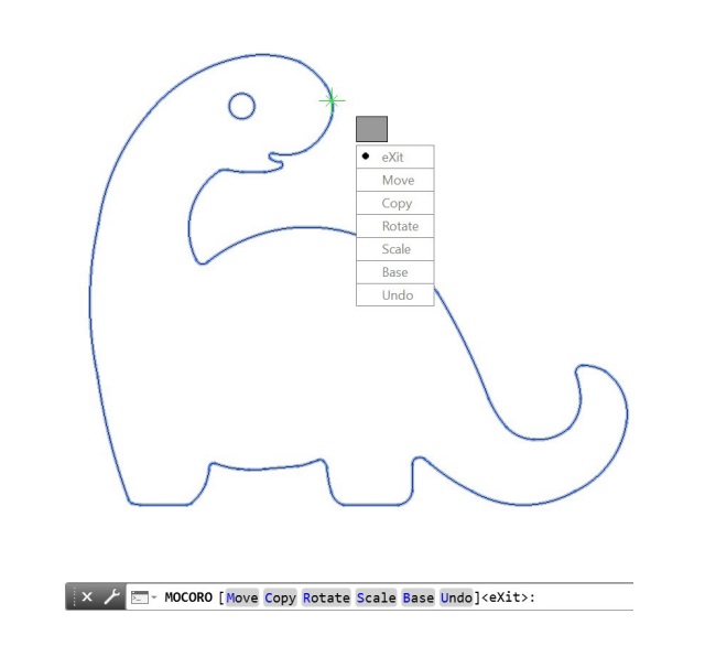
Move/Copy/Rotate
Use Express Tools, like Move/Copy/Rotate, located
in the Express Tools tab of the Ribbon to speed
up your workflow. Move/Copy/Rotate allows you
to perform any or all of these operations by only
selecting the basepoint once.
Go to the Express Tools tab of the Ribbon and click the Move/Copy/ Rotate tool. Select the object you want to move, copy, rotate, or scale.
Select a basepoint, and then follow the options on the Command line or cursor menu to select the operation you want to perform.
Each time an operation is completed, the options reappear allowing you to choose another operation using the same selected object and basepoint. If needed, you can change the basepoint by selecting the Base option
13

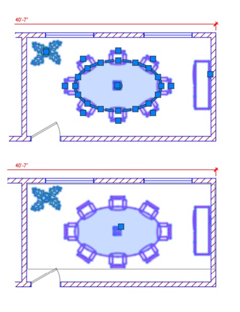
Associative Arrays
Use associative arrays, where objects within arrays
retain their relationships. It’s incredibly easy to
make adjustments to an array pattern, spacing,
and location – and much faster than changing the
location of individual objects.
Many designs contain symmetrical or repeatable patterns. Repeatable patterns, also known as arrays, can be created using the ARRAY command. Associative arrays make it easy to create rectangular and polar patterns along with distributing items along a 2D path.
Once an associative array has been created, you can:
• Replace all instances of the original object
• Replace or edit individual objects in an array
• Update the number of and distance between items in an array
14
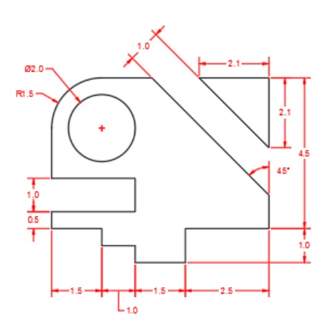
Dimensions
Save time by using the single DIM command
to create one dimension after another without
interruption and without typing multiple
commands.
Type DIM into the command line or find the Dimension tool in the Annotate tab of the Ribbon. This command allows you to achieve different results with a combination of:
• The DIM option you choose
• The type of object you hover over
• Where you hover over an object
• Where you pick or click
• What direction you move the cursor
MODIFYING
15

Match Properties
Copy properties from one object to another using
Match Properties (MATCHPROP). The types of
properties that can be matched include color, layer,
linetype, linetype scale, lineweight, plot style,
transparency, and other special properties.
- Click Home tab > Properties panel > Match Properties or type MATCHPROP into the command line.
- Select the source object from which you want to copy properties.
- Select the target objects to which you want to copy the properties, and press Enter.
16
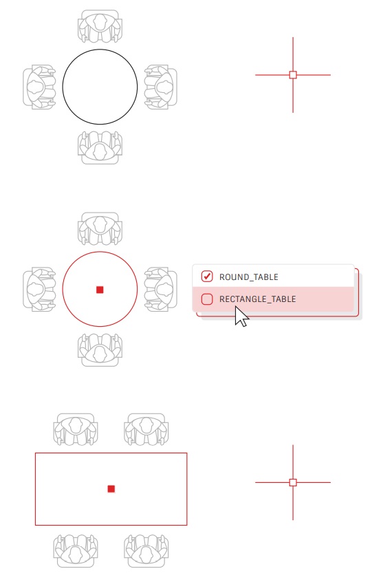
Dynamic Blocks
Save time and decrease file size by utilizing
Dynamic Blocks. Create one block that can change
shape, size, or configuration depending on their
usage instead of inserting multiple static blocks.
For example, instead of creating multiple blocks for different table types and chair settings, you can create one table block. Once the block is inserted, you can select the table type at any time. You can also define dynamic blocks that can be stretched, rotated, flipped, and more.
- Click Insert tab > Block Definition panel > Create Block.
- Back in the drawing, double-click the block and select OK on the Edit Block Definition dialog. This opens the Block Editor environment and the Block Editor Ribbon tab.
- Add constraints, actions, and parameters (rules) using the
Properties palette from within the Block Editor.
17
Group
Use the Group feature to perform multiple operations on the same objects without creating a block.
With the Group feature, you can quickly create temporary object associations. When objects are grouped together, selecting one object in the group results in all objects being selected, but each object can still be modified individually unlike a standard block.
- Select the Group command from the Groups Panel in the Home tab of the Ribbon, or type GROUP into the command line Select the objects that you want to associate together, and press Enter.
- Then, when you select any object in the group, all the grouped objects are selected. A grip is displayed at the center of the group bounding box to provide access to all grip operations.
- Add a name or description to the group for easy access later.
18

Explode Attributes
Retain your valuable attributes if you need to
explode a block by using the Express Tool “Explode
Attributes” – or type BURST into the command line.
The core AutoCAD EXPLODE command will not retain a block’s attribute information. By using the Explode Attributes tool found in the Blocks panel in the Express Tools tab of the Ribbon, you can explode a block, but retain your important attribute value.
NOTE: Explode Attributes will also preserve the layer that the block was on, along with the text style of the attribute.
19
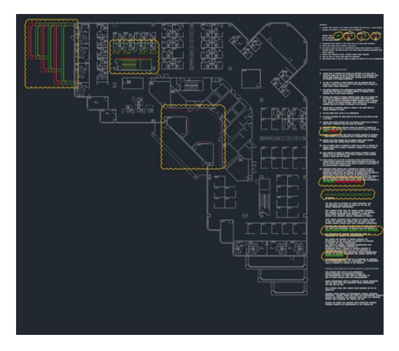
DWG Compare
Identify graphical differences between two revisions of any drawing with DWG Compare. Quickly view changes, see clashes, review constructability, and more.
There’s no need to worry about missing something – turning revision clouds on will further highlight the changes, and you can systematically cycle through each one to make sure every detail is accounted for. Start a DWG Comparison in the Collaborate Tab on the Ribbon or just type COMPARE into the command line
ANNOTATION
20
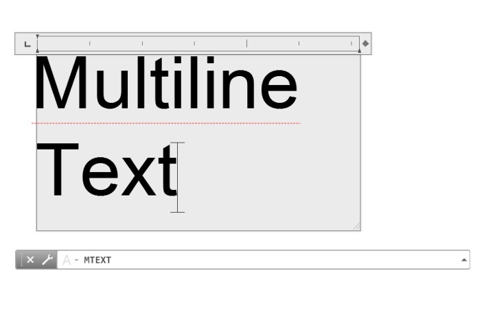
Multiline Text
Use multiline text (MTEXT) instead of single line text (TEXT) whenever possible to give you flexibility in editing your text.
You can create several paragraphs of text as a single multiline text (MTEXT) object. With the built-in editor, you can format the text appearance, columns, and boundaries.
In the Ribbon, select Annotate > Multiline Text (instead of Single Line Text) or use the MTEXT command
21
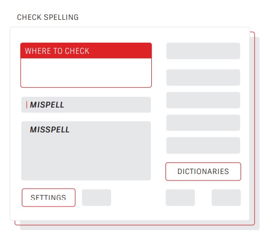
Spell Checker
Avoid embarrassing spelling errors with the spell
checker (SPELL) command. There are additional
options to check everything, just the current
space/layout, or only selected objects.
You can find the SPELL command from the Text panel of the Annotate tab of the Ribbon (or type it in the Command Line). You’ll get the Check Spelling dialog box. Click on the Settings button and you’ll get further control over what’s included in the check.
22
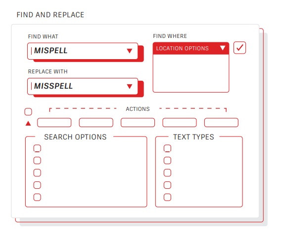
Find And Replace
Need to fix misspellings or rename certain items?
Much like in your favorite word processor, you can
Find and Replace words with ease in AutoCAD.
Start with the find text field in the Ribbon or type FIND into the
Command Line. Like the spell checker, you can choose where you want to run the check. Also, there is a dialog expansion icon that will reveal additional search options and more controls on what kind of text objects are included.
23

QuickCalc
Want to perform calculations right from within your
drawing? The QuickCalc Calculator can be used to
perform calculations within the AutoCAD drawing
environment, and the value that’s calculated can
be sent directly to the current prompt for the
command in progress.
In AutoCAD, geometric values such as distance or angular measurement are often required to draw an object. In most situations, you might know the distance or angle required to draw an object but there are times when those values are unknown and need to be calculated. Enter QC in the Command line or click on the QuickCalc tool in the Utilities panel of the Home tab.
DATA MANAGEMENT
24
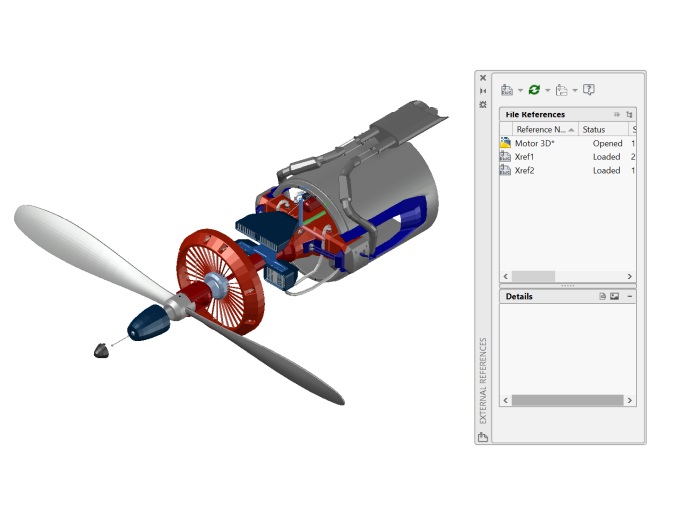
External References
Insert any drawing file as an external reference
(Xref), and changes made in the referenced drawing
are reflected automatically in the current drawing
when opened or reloaded.
Open the External References palette by using the XREF command and select the DWG icon to attach files. Attached Xrefs are linked to, but not actually inserted in, another drawing – which avoids increasing the file size.
When you attach an Xref, the default path type is set to Relative to avoid broken Xrefs in the future. If you have relative references in the current drawing and save it to a different location, AutoCAD will prompt you to update the relative paths.
25
eTransmit
When sharing DWG files containing Xrefs with
others, package and deliver groups of drawings and
related files using eTransmit. This prevents broken
links and other errors when someone else opens
your files.
Xref links will be broken when you share the file with someone else, since they do not have your referenced files.
To create a transmittal package in a folder, click Application Menu
>Publish > eTransmit or use the ETRANSMIT command. The Create Transmittal dialog box is displayed with options.
When you select a set of drawing files in a transmittal package, it automatically includes all related dependent files such as Xrefs and font files.
26
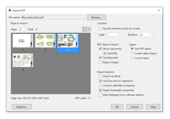
PDF Import
Import geometry, fills, raster images, and TrueType
text from a PDF file into your current drawing using
PDF Import.
PDF files are the most common file format used when exchanging design
information between designers, contractors, clients, and others. Use the PDFIMPORT command to import geometry from a PDF page into the current drawing as AutoCAD objects. You can also access PDF Import in the Insert tab of the Ribbon, then click on Import Panel > PDF Import.
After selecting a PDF file, use the Import PDF dialog box to customize your import.
27
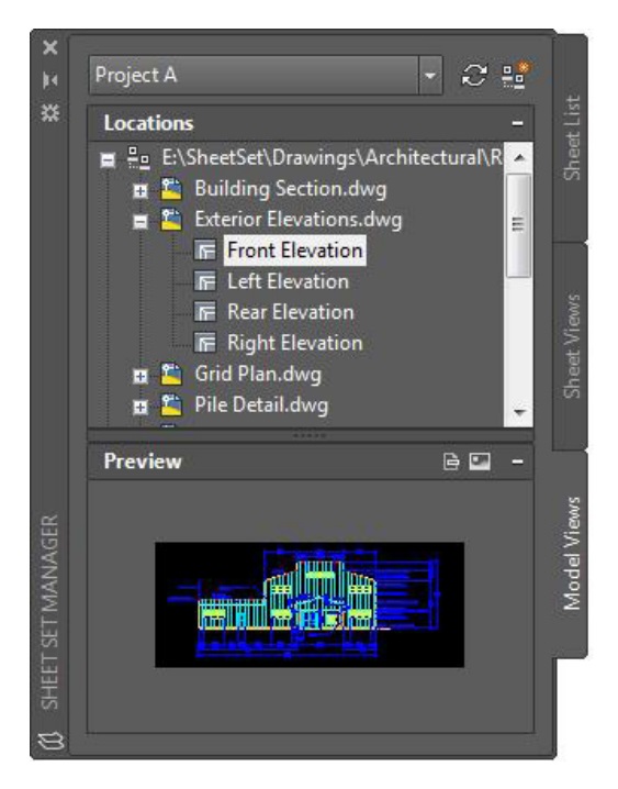
Sheet Set Manager
Keep your team on track by using the power of AutoCAD’s Sheet Set Manager. Organize and maintain your drawing layouts, file paths, and project data from one place, accessible by your entire team.
Sheet Set Manager not only functions as a file management system for your layout sheets, but it also manages saved views in both layouts and Model Space. You can easily publish part or all of the entire set, along with defining and updating title block and callout information using Fields. Getting started is easy with the Sheet Set Wizard found in the New section of the Application Menu.
ECOSYSTEM
28
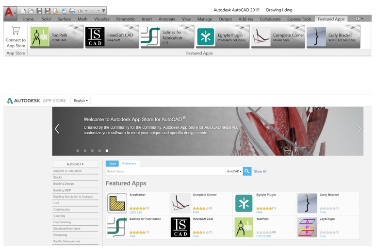
App Store
“There’s an app for that.” Explore the Autodesk App
Store for hundreds of Autodesk-approved plug-ins,
extensions, and standalone applications to make
your AutoCAD experience more productive.
You can access the Autodesk App Store from within AutoCAD in two ways. From the Ribbon, click on the Featured Apps tab, then the App Store panel and select Connect to App Store. You can also simply click on the shopping cart icon next to your login name. Either method will take you to the App Store website in your default web browser.
The featured apps banner at the top scrolls through Autodesk
recommended apps, so you can easily stay up to date. If none of the featured apps fits your current needs, you can continue your search by either keyword or your favorite publisher.
Once you’ve added your favorite apps, you can view, update, or uninstall them from the Manage Apps tool found in the Add-ins tab.
29
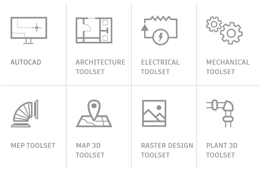
Specialized Toolsets
The quickest step towards drastic time savings: Download any included AutoCAD toolset and get thousands of intelligent objects, specialized tools, and automated processes built specifically for your industry.
All seven toolsets are included with your AutoCAD 2019 including specialized toolsets subscription.
Each toolset must be downloaded individually, via either the Autodesk Account or the Autodesk desktop app. Go to accounts.autodesk.com to sign in. From there you will be able to pick and choose what toolsets to download.
30
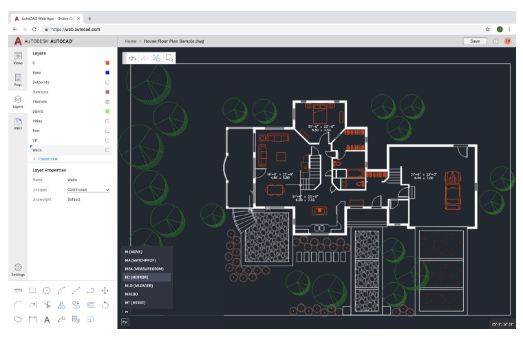
AutoCAD Web App
When you don’t have access to your office workstation, the AutoCAD web app can save you in a pinch. Just go to web.AutoCAD.com using Google Chrome browser – there’s nothing to download or install.
Log into the web app with your Autodesk ID (the same ID as your AutoCAD subscription ID). To easily save a drawing from your desktop up to the AutoCAD web or mobile apps, you can select “Save to Web & Mobile” from the AutoCAD desktop App Menu’s Save As command.
Conversely, selecting “Open From Web & Mobile” in the App Menu’s Open option lets you access the latest drawings created or edited on the AutoCAD web or mobile app.


